|
|
|
|
|
Certification
- I'm Online Chat Now
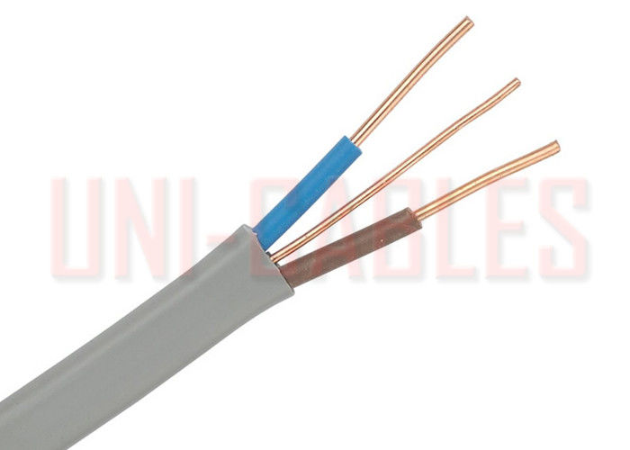
BS 6004 624 Y Flat Twin and Earth Cable Copper Conductor With Bare Earth Wire
Product Details:
Payment & Shipping Terms:
|
Detailed Product Description
| Conductor: | Copper Conductor According To BS EN 60228 | 1mm² To 2.5mm²:: | Class 1 Solid Conductor |
|---|---|---|---|
| 4mm² To 16mm²:: | Class 2 Stranded Conductor | Circuit Protection Conductor (Earth): | 4mm² To 16mm²: Class 2 Stranded Copper Conductor |
| Insulation: | PVC (Polyvinyl Chloride) | Sheath: | PVC (Polyvinyl Chloride) |
| Voltage Rating (Uo/U): | 300/500V | Temperature Rating: | -5°C To +70°C |
| Short Circuit: | +160°C | Minimum Bending Radius: | Fixed: 6 X Overall Diameter |
| Core Identification: | Brown Blue | Sheath Colour: | Grey |
| Highlight: | pvc insulated cables,insulated copper wire |
||
BS 6004 624-Y Twin and Earth PVC Electric Cable Flat Cable With Bare Earth Wire
APPLICATION
Domestic wiring cable. Can be installed in fixed installations in dry or damp premises clipped to surface, on trays or in free air where the risk of mechanical damage would not be an issue.
Suitable for laying in conduit or trunking where mechanical protection is required.
DIMENSIONS
| UNI-CABLES PART NO. |
NO. OF CORES | NOMINAL CROSS SECTIONAL AREA | CONDUCTOR CLASS | CROSS SECTIONAL AREA OF CIRCUIT PROTECTIVE CONDUCTOR | NOMINAL THICKNESS OF INSULATION | NOMINAL THICKNESS OF SHEATH | NOMINAL OVERALL DIMENSIONS | NOMINAL WEIGHT kg/km |
|
| mm² | mm² | mm | mm | mm | |||||
| UNI2010GR | 2 | 1 | 1 | 1 | 0.6 | 0.9 | 4.35 x 7.95 | 68 | |
| UNI2015GR | 2 | 1.5 | 1 | 1 | 0.7 | 0.9 | 4.85 x 8.9 | 87 | |
| UNI2025GR | 2 | 2.5 | 1 | 1.5 | 0.8 | 1 | 5.65 x 10.65 | 120 | |
| UNI2040GR | 2 | 4 | 2 | 1.5 | 0.8 | 1 | 6.3 x 11.95 | 172 | |
| UNI2060GR | 2 | 6 | 2 | 2.5 | 0.8 | 1.1 | 7.1 x 13.7 | 235 | |
| UNI210GR | 2 | 10 | 2 | 4* | 1 | 1.2 | 8.7 x 17.25 | 373 | |
| UNI216GR | 2 | 16 | 2 | 6* | 1 | 1.3 | 9.85 x 20 | 530 | |
| UNI3010GR | 3 | 1 | 1 | 1 | 06 | 0.9 | 4.35 x 9.8 | 91 | |
| UNI3015GR | 3 | 1.5 | 1 | 1 | 0.7 | 0.9 | 4.85 x 11.2 | 115 | |
*Class 2 conductors only
CONDUCTORS
Class 1 Solid Conductors for Single Core and Multi-Core Cables
| NOMINAL CROSS SECTIONAL AREA mm² |
MAXIMUM RESISTANCE OF CONDUCTOR AT 20ºC | |||||||||
| Plain Wires ohms/km |
||||||||||
| 1 | 18.1 | |||||||||
| 1.5 | 12.1 | |||||||||
| 2.5 | 7.41 | |||||||||
Class 2 Stranded Conductors for Single Core and Multi-Core Cables
| NOMINAL CROSS SECTIONAL AREA | MINIMUM NO. OF WIRES IN CONDUCTOR | MAXIMUM RESISTANCE OF CONDUCTOR AT 20ºC |
| mm² | Circular | Annealed Copper Conductor |
| Plain Wires ohms/km |
||
| 4 | 7 | 4.61 |
| 6 | 7 | 3.08 |
| 10 | 7 | 1.83 |
| 16 | 7 | 1.15 |
ELECTRICAL CHARACTERISTICS
Current Carrying Capacity and Voltage Drop
| NOMINAL CROSS SECTIONAL AREA mm² |
REFERENCE METHOD A* (IN CONDUIT IN WALL) Amps |
REFERENCE METHOD C* (CLIPPED DIRECT) Amps |
VOLTAGE DROP mv/A/m |
| 1 | 11.5 | 16 | 44 |
| 1.5 | 14.5 | 20 | 29 |
| 2.5 | 20 | 27 | 18 |
| 4 | 26 | 37 | 11 |
| 6 | 32 | 47 | 7.3 |
| 10 | 44 | 64 | 4.4 |
| 16 | 57 | 85 | 2.8 |
The above table is in accordance with 4D5 of the 17th Edition of IEE Wiring Regulations.
Note
A* For full installation method refer to Table 4A2 Installation Method 2 but for flat twin and earth cable of the 17th Edition of IEE Wiring Regulations.
C* For full installation method refer to Table 4A2 Installation Method 20 but for flat twin and earth cable of the 17th Edition of IEE Wiring Regulations.
Contact Details
Wuhan Unique Mechanical And Electrical Equipment Co.,LTD.
Contact Person: achi
Other Products
-
NYM J MultiStrand Wire PVC Electrical Cable Sheathed RM Construction For Internal Wiring
-
NYM St Insulated PVC Electrical Cable With Screen Bare Copper Conductor
-
HAR Standard Outdoor Galvanized Steel Armoured Cable , Industrial Armoured Flexible Cable
-
300 500 V H05V U Signal Single Core Wire , IEC 60332-1 Polyvinyl Chloride Wire
-
EN 50363 - 3 Standard Multicore Cable , Class 5 Conductor Armored Core Cable
-
H07V K PVC Electrical Cable Transformer 450 750V For Light Application